
¥ 1495.00
¥ 1495.00
¥ 1495.00
¥ 1495.00
¥ 1495.00
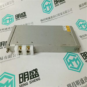
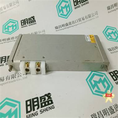
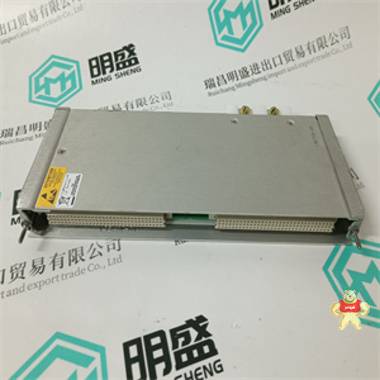
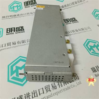
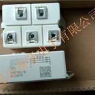
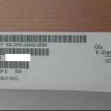
易卖工控网(www.ymgk.com)提供”136719-01模块现货”,产品详情:品牌/厂家:、型号:136719-01、成色:全新、货期:现货 1天内发货、保修:180天,更多产品详情就上易卖工控网。
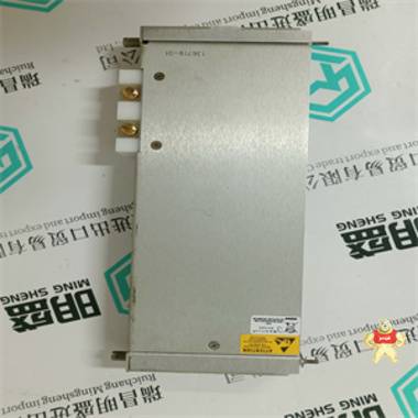
136719-01
1.4.4 CS31系统总线的连接
通过以下方式连接到CS31系统总线:
3极可拆卸接线板。请注意:
·所有AC31设备,无论是主设备还是从设备,都连接到双绞线总线,如
跟随:
通过总线一个核心的环路使用
所有待连接设备的总线1端子
CS31系统总线。
通过总线的另一个核心,使用
所有待连接设备的总线2端子
连接至CS31系统总线。
·如果基本单元07 KR 91位于开头或
在总线线路的末端,总线端接电阻器
(120 W)必须在
总线1和总线2端子。
·双绞线母线的屏蔽环穿过
通过连接到CS31系统总线的所有设备的屏蔽端子。
·CS31系统总线的处理如所述
详见第2卷系统数据。
终端分配:
24屏蔽
25总线2
26总线1
信号名称
端子号
内部24 V直流电源
电源必须接地(带
开关柜接地)
习惯于
1.4.5信号电源的24 V输出电压
输入
基本单元07 KR 91提供单独的24 V DC
提供20个数字输入信号的电压输出
(仅用于此目的)。
该24 V输出电压仅在外部24 V时使用
直流电源装置不可用。
内部24 V电源防过载。这个
24 V输出电压约可再次运行。
过载消除后2分钟。
图111:CS31系统总线的分配
界面
终端分配
32 ZP1参考电位(OV),负极
电源极
33 ZP1与端子32相同(内部
短路)
34 UP1+24 V,电源正极
图112:
输出电压
4 07 KR 91/电气连接1-12 Advant控制器31/发布日期:10.98
绿色LED
特征:
·20个数字输入分为3组。
·3组E 62,00。。。E 62,07,E 62,08。。E 62,15和
E 63,00。。。E 63,03与每个
另外
·输入与正逻辑中的24 V信号一起工作
(信号1表示+24 V)。
·输入信号的延迟为7毫秒(另请参见
以下)
端子2和3处的输入信号
端子2
·用作正常输入信号:
该信号在操作数E 62,00的用户程序中可用。信号延迟时间为7毫秒。
执行操作数E 62,00的更新
在每个程序周期开始之前。
·用作高速输入信号:
该信号在操作数E 63,14的用户程序中可用。信号延迟时间为0.02 ms。
执行操作数E 63,14的更新
在每个程序周期开始之前。
在双端口RAM(DPR)中,该信号在每个CS31总线报文后更新。借助功能块WOL,可以在双通道中读取该信号
端口RAM(字地址C000:1FEH,位14)。
·用于高速计数器:
该信号用作
高速计数器。
标识符
终端
标识符
参考电位
ZP1.0、ZP1.1和ZP1.2
图113:20个数字输入的分配
1.4.6数字输入的连接
下图显示了20个数字输入的配置。
端子3
·用作正常输入信号:
该信号在操作数E 62,01的用户程序中可用。信号延迟时间为7毫秒。
执行操作数E 62,01的更新
在每个程序周期开始之前。
·用作高速输入信号:
该信号在用户程序的操作数E 63,15中可用。信号延迟时间为0.02 ms。
执行操作数E 63,15的更新
在每个程序周期开始之前。
在双端口RAM(DPR)中,该信号在每个CS31总线报文后更新。借助功能块WOL,可以在双通道中读取该信号
端口RAM(字地址C000:1FEH,位15)。
·用于高速计数器:
该信号用作高速的启用输入
柜台
136719-01
136719-01
1.4.4 Connection for CS31 system bus The connection to the CS31 system bus is made by means of a 3-pole detachable terminal block. Please observe: · All of the AC31 devices, whether master or slave devices, are connected to the twisted-pair bus line as follows: Loop through one core of the bus line is using the BUS1 terminals of all devices to be connected to the CS31 system bus. Loop through the other core of the bus line using the BUS2 terminals of all devices to be connected to the CS31 system bus. · If the basic unit 07 KR 91 is located at the beginning or at the end of the bus line, the bus terminating resistor (120 W) has to be connected additionally between the BUS1 and BUS2 terminals. · The shield of the twisted-pair bus line is looped through via the SHIELD terminals of all the devices to be connected to the CS31 system bus. · The handling of the CS31 system bus is described in detail in Volume 2, System data. Terminal assignment: 24 SHIELD 25 BUS2 26 BUS1 Signal name Terminal number The internal 24 V DC power supply must be earthed (with switch cabinet earthing) only if used. 1.4.5 24 V output voltage for the signal supply of the inputs The basic unit 07 KR 91 provides a separate 24 V DC voltage output for the supply of the 20 digital input signals (for this purpose only). This 24 V output voltage is used only if an external 24 V DC power supply unit is not available. The internal 24 V power supply is overload-proof. The 24 V output voltage is ready for operation again approx. 2 minutes after an overload has been eliminated. Fig. 111: Assignment of the CS31 system bus interface Terminal assignment 32 ZP1 Reference potential (OV), negative pole of power source 33 ZP1 Identical to terminal 32 (internally shorted) 34 UP1 +24 V, positve pole of power source Fig. 112: Assignment of the terminal block for the output voltage 4 07 KR 91 / Electrical connection 1-12 Advant Controller 31 / issued: 10.98 Green LEDs Features: · The 20 digital inputs are arranged in 3 groups. · The 3 groups E 62,00...E 62,07, E 62,08..E 62,15 and E 63,00...E 63,03 are electrically isolated from each other. · The inputs work with 24 V signal in positive logic (signal 1 means +24 V). · The delays of the input signals are 7 ms (see also below) Input signals at the terminals 2 and 3 Terminal 2 · Use as normal input signal: The signal is available in the user program in the operand E 62,00. The signal delay time is 7 ms. The updating of the operand E 62,00 is performed before the start of each program cycle. · Use as high-speed input signal: The signal is available in the user program in the operand E 63,14. The signal delay time is 0.02 ms. The updating of the operand E 63,14 is performed before the start of each program cycle. In the Dual Port RAM (DPR) this signal is updated after each CS31 bus telegram. With the aid of the function block WOL this signal can be read in the Dual Port RAM (word address C000:1FEH, bit 14). · Use for the high-speed counter: The signal is used as counting input (10 kHz) for the high-speed counter. Identifiers Terminals Identifiers Reference potentials ZP1.0, ZP1.1 and ZP1.2 Fig. 113: Assignment of the 20 digital inputs 1.4.6 Connection of the digital inputs The following illustration shows the configuration of the 20 digital inputs. Terminal 3 · Use as normal input signal: The signal is available in the user program in the operand E 62,01. The signal delay time is 7 ms. The updating of the operand E 62,01 is performed before the start of each program cycle. · Use as high-speed input signal: The signal is available in the user program in the operand E 63,15. The signal delay time is 0.02 ms. The updating of the operand E 63,15 is performed before the start of each program cycle. In the Dual Port RAM (DPR) this signal is updated after each CS31 bus telegram. With the aid of the function block WOL this signal can be read in the Dual Port RAM (word address C000:1FEH, bit 15). · Use for the high-speed counter: The signal is used as enable input for the high-speed counter.


闽公网安备 35020302034948号

 发布询价成功


 QQ咨询
QQ咨询
 )
)


 当前商品暂无此评价~


 18059884802


 记住账号
记住账号